 All available external PODs
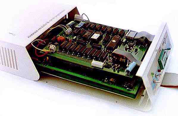
The DENEB Full Stand-Alone Serial Emulator is essential
for the designer and production of microprocessor systems, it is provided
with a serial interface and can easily be connected with terminals, personal
computers and hosts; furthermore the included eprom programmer allow the
programmation of well-know eproms.
Introduction
With this programme it is possible to run programmes step-by-step
in machine language and verify the contents of each of the various registers
and the memory data in order to understand where eventual bad functioning
of the software that you are testing is occuring. To work with an emulator
on a microprocessor board, is to assemble the programme, programme
an EPROM memory, then insert this in the board and restart the
system. At this point there are two possibilities: or the programme works
perfectly, very unlikely if it is quite consistent, or it will stop for
some reason. With the help of this instrument, it is possible to trace
the error in a very short time, by simply running the programme step-by-step
and verifying how the registers vary or by inserting breakpoints in
specific areas and running the programme in Real Time. From this brief
description of how the emulator is used, you will understand that it is
not only a help, but indeed absolutely necessary in the development
of microprocessor projects.
One of the strong points of the DENEB emulator software, is the C
Debugger. With this it is possible to debug any C source developed
by the user for the target. The management of the breakpoints can be performed
directly on the lines of the C programme and, by means of the special Watch,
it is possible to monitor any symbol in “Real Time”.
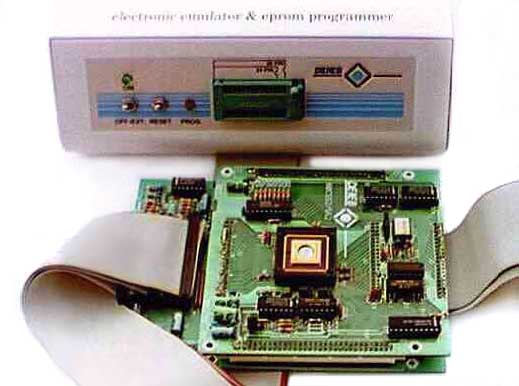
The
Universal Emulator DENEB
The DENEB® P2 is made up of two separate parts:
the emulator and the eprom programmer (for 2732..27512-87x51,
68HC11, 80552).
-
It's made up of 5 or 6* boards (see diagram):
-
the monitor and eprom-programmer board;
-
the universal 8 bit or 16 bit slave board;
-
the universal 8 bit or 16 bit base board;
-
the emulation POD containing the µP for real-time
and maximum speed emulation.
-
* a real-time-trace board;
-
Board containing eprom programmer's textool, the ON/OFF and Reset switch,
and the ON and PROG leds.
-
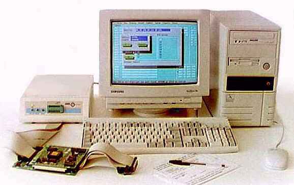
The emulator works from the serial port of any IBM-PC,AT or compatible
in a full stand-alone mode at a software programmable baud-rate.
Common
technical characteristics of all micros emulated into 8 bit and 16 bit
P2 Series:
-
The microprocessor emulation occurs without the use of any of the micro's
resources: there are in fact two µPs in the emulator, one of them
manages the monitor, the eprom programmer and the slave µP, the other
is the emulation slave micro.
-
The emulation occurs in real-time and at the max speed allowed by the µP.
For that reason the emulation µP is located in the external pod,
with the probe close to the target (only few centimetres), furthermore
all the µP signals go out directly to the probe without intermediate
buffers (a few control signals in some micros can be buffered, or not,
by setting the relative jumpers).
-
The power supply of the emulation µP can be set to internal or external
by a jumper present in every pod. It is advisable to power the emulation
micro with the external target power (setting the relative power jumper
to external), so that switching on and off the target will not produce
conflicts with peripherals connected to the same micro. If the target is
not present and it is necessary however to do software emulation, then
it is possible to work by setting the power jumper to internal. It is also
possible to emulate the external target with the power jumper set to internal,
but in this case, with the external target switched off, the CMOS micro
internally powered by the emulator will improperly supply the external
hardware, thereby falsifying the working conditions.
-
The 8-16 bit P2 series emulator has 128Kx16 RAM of internal emulation
mappable with 8K block resolution (for all µPs that address more
than 64K), when it is used with an 8 bit µP, the ram is mapped as
in the P1 series; furthermore it is provided with 8 hardware breakpoints
for real-time emulation with the clock settable to internal or external.
-
Banking: 16 banks of 64K for 8 bit processors, 256 banks of 64K
for 16 bit processors.
-
Trace: 32Kx64bit trace buffer with internal/external clock, internal/external
trigger, pre/center/post trigger with 8K counter, 8 clips and a supplementary
external breakpoint. “Trigger” and “Level” outputs.
-
The emulation is completly symbolic.
-
On-line assembler and disassembler.
-
In-memory display/modify/movers.
-
Display/modify registers.
New optional:
-
Performance Analyser.
-
Breakpoints linked to the data contents (at the max. emulation speed).
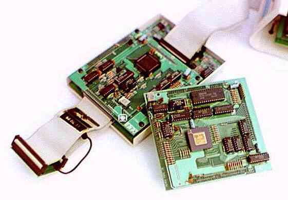
Replacing
the microprocessor's POD and 8-16 bit passage
The user that buys a DENEB universal emulator can work with different
micros, depending on the project, without completely replacing the emulator,
but simply buying the POD emulating the required micro and substituting
this in the basic setup.
-
To go from one micro to another just substitute the external emulation
pod and load the monitor file into emulator memory, that management the
new µP .
Single-chip 87x51, 68HC11 and 80552 programmer
adaptor
Not only can the eprom programmer contained in the emulator program
accept the 2732-512 eprom, but also the 87C51, 8751, 68HC11 or 80552 single-chip
by means of the adaptor for the textool socket on the front panel of the
emulator.
DENEB P2 Series Firmware

A hardware/software communication interface called the Micro Handler
has been specially designed. The software is customized for each family
of microprocessors emulated by the P2 series according to the different
technical characteristics, and it enables the serial dialogue between the
emulator and any MS-DOS/WINDOWS 3.x/WINDOWS 95 computer.
-
The interface accepts all numeric data (addresses, registers, memory
data, etc.) in the decimal, hexadecimal, octal and
binary systems. The emulator manages IAR-SYMBOLIC format
symbols. The symbol can be entered either in small or capital
letters. A symbol entered in small letters will be considered
differently to one entered in capitals.
-
Single characters must always be enclosed in inverted commas (‘
’).
-
An array must be enclosed in { }, each single element can be a numeric
value, a single character and/or an algebraic function and each element
must be separated by a comma (eg.{5,100h,’c’,563+4h}).
-
In each input area, it is possible to specify the values in numeric form
or in algebraic form (operators: +-*/) using also the C symbols
loaded in the memory.
-
To move quickly around the CPU area it is possible to use the mouse. By
double clicking on an address or register a box will be opened in
which the data can be inserted.
-
With the right key of the mouse it is possible to open a context menu
within the dump, trace and breakpoint areas in which special functions
are contained. These will be explained later in the relative sections.
The
Trace board
The trace is an optional board incorporated in the emulator, that records
the various events of the microprocessor and the various logic levels present
on a series of external clips. This board acquires the data (frame)
at every clock cycle and feeds it into an internal buffer to analyse it.
The 56 bits of data acquired are distributed as follows:
-
16 bit for the data bus.
-
24 bit for the address bus.
-
16 bit for the control signals.
-
8 external clips.
The first three group of bits is read by the probe while the 8 clips are
read by one external connector (CON1). At each clock edge (internal or
external) the 64 bit word is memorized in 8 chips of 32Kx8 static
ram, the trace buffer counter is then increased ready for a new
acquisition.
The trace board acquisition clock can be internal or external:
-
if internal it can be qualified by the control signals of the microprocessor
by means of the “Set up of trace...” and the acquisition edge used is the
rising edge, as the addresses are already stable in this;
-
if external it is possible to choose between the rising edge, by putting
the clock on the CLKEXTV clip of CON1, or falling edge by putting the clock
on the CLKEXTD clip of the same CON1.
The only condition to respect is that the time between two edges must be
>100ns.
With respect to other emulators, the DENEB Trace acquires frame not
only with the “Go” command but also with “Trace into”. Furthermore,
with each emulation, the ram counter is not zeroed, thereby having the
possibility to conserve all the data acquired previously.
Once the recording has been carried out you can view the data
by opening the “Trace” window from “View” menu.
The data acquisition of the trace will begin the moment the micro carries
out the first instruction; all the operations that occur from the beginning
of the emulation to the first breakpoint are recorded as Pre Trigger
events (First frame).
When a breakpoint is encountered (that is the trace trigger, that can
be internal or external) the trace sets a counter and continue to record
all the successive operations of the µP for a number of clock cycles
(internal or external) equal to the setting of the trace counter; these
operations are recorded as Post Trigger events (Last frame).
When the counter has completely run out, the emulator will stop and the
trace will terminate the acquisition.
All available external pods
|